The internet of things world is here, but implementing systems that are compatible does not always seem tangible at first. However, I've learnt that a basic implementation is achievable when using small, inexpensive technology with a low level of entry. In this article, I will demonstrate how you can control your own kitchen kettle over the internet, using the novel Raspberry Pi micro-computer.

While doing a course in control engineering, I realised that I could use control techniques and a Raspberry Pi (Pi) to create software that automatically adjusts the temperatures of my craft beer brewing apparatus. Controlling the temperature in a brewery is really important because the enzymes and yeast can only produce the sugar and alcohol required for beer at precise temperature ranges.
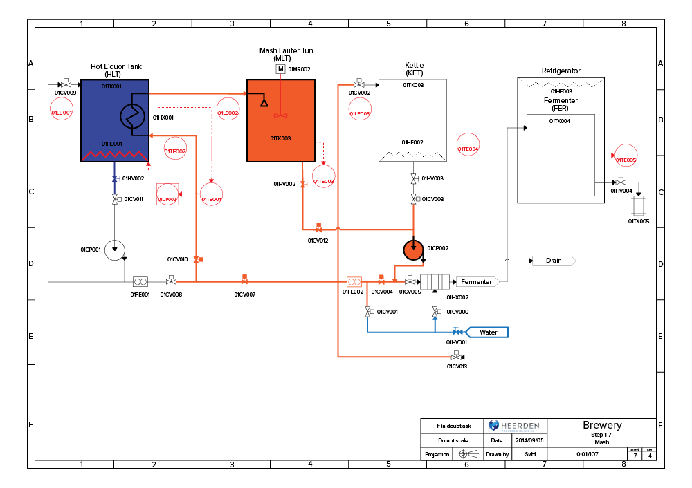
A home brewing system consists of the following parts:
- A hot liquid tank, like an urn, to indirectly heat the brewing solution with water. The temperature must be precisely manipulated here, otherwise it will get burnt.
- A mash lauter tun to extract sugar barley which will eventually become the alcohol.
- A "kettle" where the hops and extra ingredients are added to complete the brewing solution.
- A refrigerator to cool the brewing solution so that the yeast can properly ferment. The temperature here must also be precisely manipulated for the yeast to function correctly.
In the end, my home brewery looked like this:
The brewing process can take a long time to complete, so it is convenient to have access to control this system while not at home. For this reason, I decided to add one more feature which would allow me to control the system over the internet.
To make this tutorial easier to follow, I will explain how I set up the control system for the mash lauter tun, which works the same as an everyday kitchen kettle.
Setting up the temperature controller
Required hardware
Apart from the Raspberry Pi , the following pieces of hardware are required:
- A waterproof DS18B20 temperature sensor to measure the temperature of the solution.
- A 100 ohm resistor for the temperature probe circuit.
- A 5V power supply, or a standard cell phone charger, with a micro USB connector to supply power to the Pi.
- A plug to connect the whole system to a high-voltage (230 V), alternating current (AC), wall socket. This will supply the high-voltage system with power.
- 2.5 mm wires for AC supply.
- 0.5 mm wires for direct current (DC) supply.
- An ethernet cable or WiFi dongle since the purpose of the system is connect it to the internet. The use of an ethernet cable is recommended, as it is a more reliable connection for a micro-project like this.
- An internet router with multiple ports to help you create a home network.
- A solid state relay (SSR) with a DC source (from the Pi) to control the AC supply (to the kettle).
- A standard coffee kettle, which we will control its heating element.
- Working with high-voltage is always dangerous! It is important to use the following hardware as a safety precaution:
- A circuit breaker to trip the power on a short circuit.
- A ground fault interrupter (GFI) which trips the power when there is a small drop in current.
It's particularly important to be super careful here because we are dealing with electricity and water - which conducts electricity easily!
Setup of hardware
While setting up the electrical circuit, if you are not sure whether your setup is correct, rather consult an electrician first! Incorrect wiring of a high-voltage line could result in hardware damage, shock or even death.
The figure below shows you how I connected the electrical circuit:
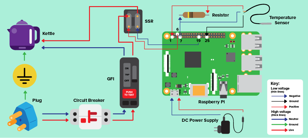
There are two main elements to set up:
- The high-voltage system which contains all of the hardware requiring an AC power source.
- The low voltage system for hardware requiring a DC power source.
High-voltage connections:
- Connect the wall plug to the circuit breaker.
- Connect the circuit breaker to the GFI. Note that the ground wire bypasses the GFI, but it is important to make sure that the ground wire is connected to all of your high-voltage hardware.
- Connect the GFI to your DC power supply.
- Connect the following wires from the GFI to the kettle:
- Live wire (red) to the first live connector of the SSR.
- Neutral wire (blue) to the neutral wire of the kettle.
- Ground wire (yellow) to the ground wire of the kettle.
- The second live connector of the SSR connects to the live wire of the kettle.
Low-voltage connections:
- Connect the Pi to the DC power supply.
- Connect the temperature sensor and resistor to the Pi's GPIO (General Purpose Input/Output) pin (7), ground pin (25) and power pin (1), as shown in the circuit diagram above.
- Connect the Pi to the SSR with a GPIO pin (19) and a ground pin (6).
- Insert the sensor into the top of the kettle. Don't worry, the wiring of this sensor is waterproof and heat-resistant.
Before we can test the hardware setup, we need to set up the software. Let's take a look at what you will need to do that.
Required software
The software allows us to interact with the hardware that we have configured. The following software systems must be installed on the Pi:
- Firstly, the Raspbian operating system is a derivative of Linux Debian, and is optimised to give the best performance on the Pi's ARM processor. It runs all of the Pi processes and facilitates any interactions with external hardware.
- The control software RasPiBrew is the highest-rated, open-source, brewing control software on Github. The core of this control software consists of a small Python Flask web server that has been configured to perform the following tasks:
- Read and write to the Pi's GPIO pins.
- Use the inputs and outputs in a PID (Proportional Integral Differential) control algorithm.
- Display the results on a graph in your browser.
- A SSH (Secure Shell) client software, like Putty, is used to connect to the Pi from your PC.
Setup of software
While there is an official software guide for the RasPiBrew software, I have summarised the most important steps here:
- Connect the Pi to the internet either with a ethernet cable or WiFi dongle. If you use an ethernet cable then no further steps are needed, to connect over WiFi follow these additional steps.
- Get the IP address of the Pi that you will use on your home network and later the internet. There are several methods that you can use to do this:
- Read the IP from your router's config screen.
- Otherwise, if you have a HDMI monitor connected to the Pi, run the following command in the terminal to get the IP:
$ ifconfig
- SSH into the Pi with Putty, to remotely login into the Pi.
- Run the following commands in the Putty terminal to install RasPiBrew on the Pi:
$ cd /var
$ mkdir www
$ cd www
$ git clone https://github.com/steve71/RasPiBrew.git
- Make sure that the DS18B20 temperature sensor is connected. The sensor itself uses the 1-Wire protocol which must be activated with the following command:
$ sudo modprobe w1-gpio
- You need a sensor ID so that the Pi can identify which hardware it should receive temperature readings from. It will simply display the file name. Get the sensor ID by adding this command into the terminal:
$ cd /sys/bus/w1/devices/
- To allow the software to receive temperature readings from the temperature sensor, add this ID to the RasPiBrew config file:
$ cd /var/www/RasPiBrew
$ sudo nano config.txt
Test the current setup
With the primary hardware and software configured, we should test whether everything works together.
- To start RasPiBrew, use Putty to run the command below in the terminal:
$ cd /var/www/RasPiBrew
$ python raspibrew.py
- Type the following address into your browser to get a local version of the control software:
http://the_pi_ip_address:5000
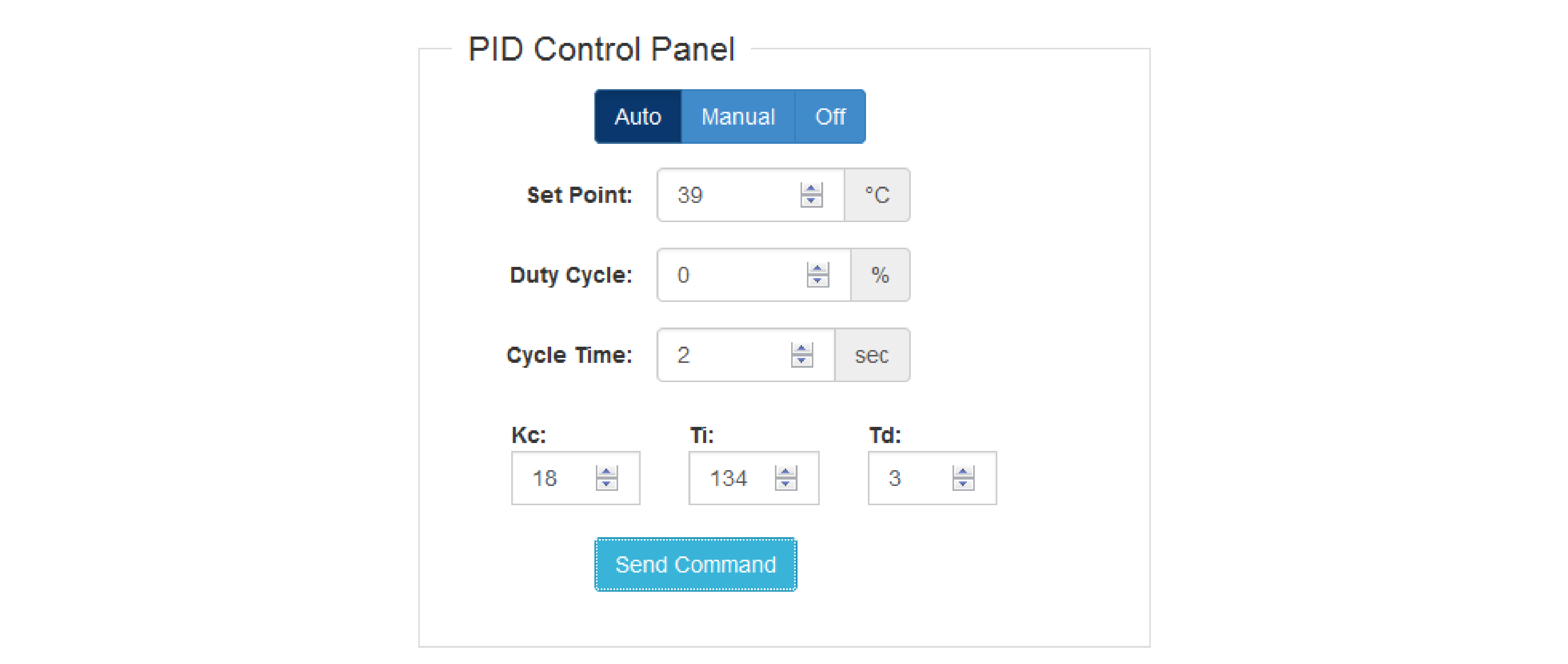
- A Flask webpage, as seen in the image below, will be shown. The settings on this page are used to control the temperature, which will be explained in detail later in the tutorial.
- You are now able to control your kettle on your local, home network! Details on how to operate it will be explained in the following sections.
Setup internet connection
The grand vision for this project is to finally control the system over the internet. One way to do this is to create your own web server. These steps will guide you towards doing that:
- As seen in the previous section, the control software already displays the control results on your browser through a port on your local network.
- Your router needs to be configured to display the control page to the rest of the world. I have used a TP-Link C20, since it is a great router. Note that the configuration might be a bit different if you use a different router.
- Start by logging into your router's configuration page to set up the internet connection.
- Setup a No-IP account, or any other dynamic IP service supported by your router. This will allow you to assign a static url and website address to your home dynamic IP (e.g. 101.202.303.44) provided by your internet service provider (ISP).
- Add your dynamic IP address to the No-IP account.
- Pick one of their free domains and choose a url to use, for example 'temperaturecontrol.ddns.net'.
- Link the No-IP account to your router, or use a similar service that is supported by your router. This will update the website address whenever the your dynamic home IP is changed by your ISP.
- Configure a virtual network on the router to translate the internal port of the Pi to your outside IP address, or the URL registered with No-IP. Note that this network architecture has limited security, but it is beyond the scope of the article to set up an enterprise-ready network.
- With your control software already running from the previous section, you should now be able to access the controller page from anywhere in the world with the No-IP url.
Running the temperature controller
Now that you've set everything up, and testeed that all of the components work together, let's boil some water! Since the control software is running over the internet, you can see the PID control panel in your browser. Here's how you use the specific settings.
- The mode of the controller needs to be set to "Auto" first, so that the Pi can take control of all connected hardware.
- Enter the set point (SP) temperature to the temperature that you want the kettle to be heated to. The natural boiling point of water is 93.7℃ at altitude (Johannesburg) and 100℃ at sea level.
- Leave the cycle time at 2 seconds for now, this will be explained further in the next section.
- Leave the three PID algorithm constants Kp, Ki and Td set to the default values for now. Do not worry about the details now because you can calibrate it according to your exact system later.
- Press "Send Command" to see how quickly and accurately the kettle is controlled.
- To stop the kettle, select "Off" and then "Send Command" again.
- You are now able to control your kettle while you drive home!
Further calibrating the temperature controller
It is more than adequate to use the default constants provided in the previous section for temperature control. But, if you do want to go further and set up your controller for your exact system, follow the instructions in this section.
The cycle time, Kp, Ki and Td default values that are preprogrammed in the controller already work well for most small, temperature control systems. However, every physical system remains unique. This means that you might need to calibrate these settings to achieve quicker response times from the controller as well as more accurate temperature control.
To understand the controller settings, I will explain the PID algorithm first. The PID equation is as follows:
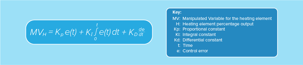

The cycle time will determine how often the code is executed. We require this equation in a discrete form that can be calculated by the Pi. The pseudocode for the algorithm is as follows:
// t current time
// t-1 previous time cycle
// difference in time
dt = t – t-1
// error between the SP and PV at the current time
et = SPt - PVt
// difference in error at current time and previous time cycle, for integral function
det = et - et-1
// difference in the error difference at current time and previous time cycle, for differential function
det = det - det-1
// main discrete PID algorithm
MVt = MVt-1 + Kp * (det + dt/Ki * et + Td/dt * ddet)
There are three constants in the main PID algorithm that need to be be set, Ti, Td and Td. While there are several methods that can be used to calculate the constants, the Ziegler-Nichols Open Loop method is easy to implement. This method provides several formulas, but you first need to measure specific data points.
- To start this calibration, we place the control software in manual mode.
- Set the heat output of the kettle to 100% and let it boil for at least a minute, to get good data point for the calibration.
- The control software will plot the change in temperature and power of the kettle, or heat, over time. This can be seen in the image below:
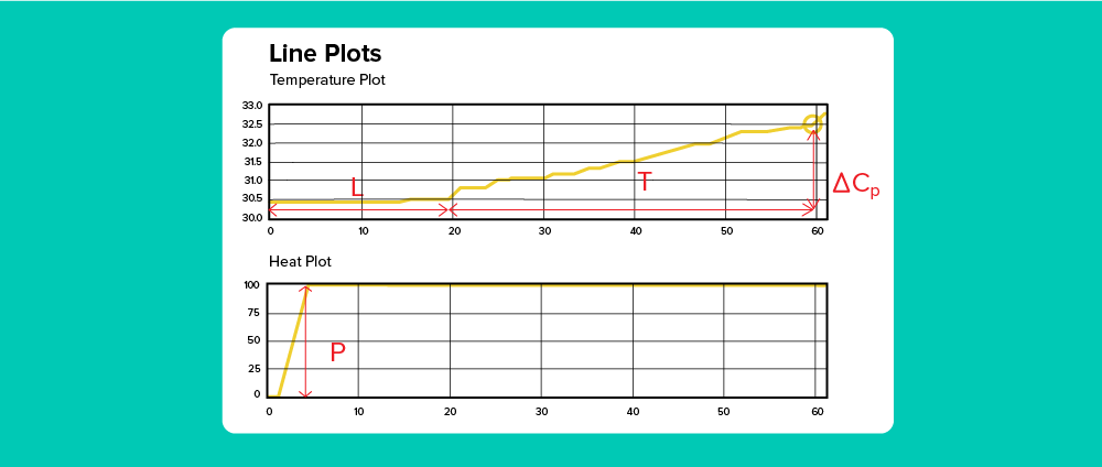
- The variables have been marked and then measured on the line plot. We will use these measurements in the Ziegler-Nichols method. Example values from the above plot have been given in brackets.
- L - Lag time for the kettle to respond to changes imposed by the controller (20s)
- T - The time difference between the lag time and our 1-minute test time (40s)
- P - Step change in the heat plot (100)
- ∆Cp - The change in temperature (2℃)
- Use the measured variables to calculate the PID algorithm constants:
- N = ∆Cp / T (reaction time = 0.05)
- R = NL / ∆Cp (lag time = 0.5)
- Kc = 1.2 (P / NL) (120)
- Ti = 2.0L (40)
- Td = 0.5L (10)
Note that you can still adjust these constants by a few decimal positions to make the controller faster or more accurate. For example, by increasing the Kc value the response time for the controller will be faster and increasing the Ti and Td will improve the accuracy.
Improvements and recommendations
I am currently writing a new control system, based on a ASP.NET Core web server, that will be flexible enough to control all of my brewery's hardware. The hardware will include pumps, control valves, heat elements (like our kettle), a cooling element for controlling the refrigerator, level sensors and temperature sensors.
I have demonstrated how to connect and control a kettle over the internet with the help of the Raspberry Pi and some other hardware and software. You could also use this same software to control relays, like switching on your house lights or to control the temperature in a sous vide system.
Most of the building blocks needed to connect devices over the internet are already in most developer's toolkits. The stack just needs to be put together!
Schalk's career started off as a process engineer, but destiny called with the Raspberry Pi which opened up a bigger world of IT. He is now a software engineer who loves to discover and create new systems every day...